PART DIPPING ARM
MARCH 2023 - MARCH 2025
MICROCHIP TECHNOLOGIES INC.

Background:
One of the biggest projects I had while working at Microchip Technologies was repairing the site's automated solder dip machine. The biggest issue was the part holder arm itself, which had a few design flaws. This caused unnecessary damage to the arm, leading to additional and often unnecessary replacement costs. This also left the machine out of commission until replacement parts could arrive.

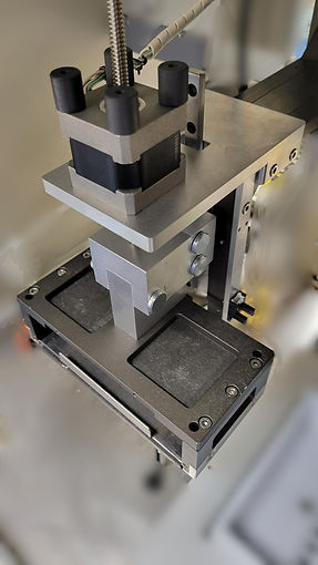
Cooling Fan
Wire Holder
Actuator Cover
Parts Holder Platform


Actuator Screw
Guide Rail
Rail Bearings
Screw Holder
Connector
Sensors
Zoomed in view
Key problems included:
-
The arm acting as a lever against the rail and rail bearings, destroying them twice before.
-
The actuator screw bending due to stress caused by misalignment and as being the sole anchor point for the arm.

Result of excessive force, steel rail cracked into 3 pieces
2.
Actuator Screw
Rail Center

Caused a clockwise tilt, leading to a bent screw
1.

Arm Weight
Excessive Force on Rail
Various Sketches:
Rough sketches and dimensioning was the key to determining tolerances and design ideas. SolidWorks became the medium through which ideas were tested. Assemblies of my ideas led to effective prototyping. Not pretty, but very effective.
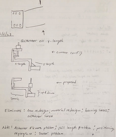


Sketches for the prototype. Heavy focus on actuator placement and reinforcement, and arm support.


Sketches for a redesign consisting of all machined parts.
3D Prototype:
Our site didn't have a 3D printer, so I printed parts off site at a makerspace. The only plastics available for use were PETG and PLA. In order to test various configurations, I opted not to have parts made online in order to save time and money.
I printed parts with more complex geometry while had simplistic and load bearing parts machined.
The heat tolerance of PETG made it ideal for parts closer to the front of the arm as they would be exposed to heat and melted solder. PLA was used towards the back to elevate wires for better horizontal rail clearance.
The arm is now bolted to the back panel, stabilizing the arm.

3D Printed Parts
Machined Parts
-
Actuator and Rail moved forward
-
Load now in line with screw
-
Cooling Fan moved forward
-
Sensors moved forward
-
Wires are now elevated towards the back
Key Features:
-
Actuator holder has cooling holes and fan mount to prevent overheating while holding it in line with the platform's center.
-
Screw guide provides additional stability and alignment, reducing stress.
-
Machined connector holds platform, screw, and rail bearing together.
-
Back piece provides additional reinforcement against arm's weight.

3D printed parts allowed for rapid prototyping to fix structural and tolerance issues
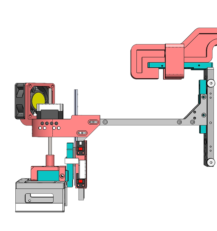
Side View
1.
2.
3.
4.
Final Machined Design:
While the 3D printed prototype did work well, maintenance was difficult due to the assembly process of the arm. If work needed to be done on the rails or the actuator, it was extremely difficult to gain access. Additionally, certain components such as the fan were unnecessary because the actuator wasn't doing as much work anymore. The old configuration had the actuator holding the whole arm at all times, causing the actuator to heat up and then require the fan.
My objective with the final design was to simplify it as much as possible, keeping basic shapes so machining is faster in the future. The central focus of this design was to have components interlock and detach so maintenance was simpler.
With precise tolerancing and measurement, a cleaner and more effective design was achieved.
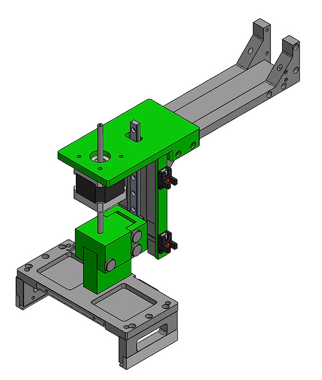
Machined Parts
-
Interlocking components with pins for easy maintenance
-
Moved Actuator forward and higher
-
Removed fan, additional cooling unnecessary
-
Adjusted fixture height for optimal universal clearance

1.
2.
3.
4.

Exploded View
Side View
Key Features:
-
Actuator holder in line with platform center, but now open for better air flow.
-
Actuator connector attaches to screw
-
Cart connector attaches to rail bearing
-
Platform connector attaches to platform
Summary of Work:
-
Performed Root Cause Analysis and Needs Analysis to determine failure points and design requirements.
-
Brainstormed possible low cost and time efficient solutions to repair the arm subsystem.
-
3D modeled the entire preexisting arm in SolidWorks for easier redesign conceptualization.
-
Performed FEA using ANSYS to determine stress on existing arm design.
-
Fabricated 3D printed components for low stress parts.
-
Utilized GD&T principles to produce drawings for machined high stress parts.
Results:
Arm moves as previously designed with no issues. Additionally, wires in the back have greater clearance and arm has a greater range of motion. Redesign saved potential replacement costs of almost $1000 and wait times of nearly 8 weeks. Interlocking components provide easy access for maintenance. The arm's redesign brought the Solder Dip back up and running for part dipping.